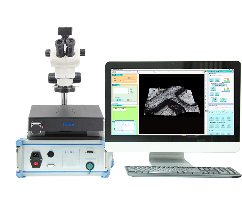
Choose a motorized stereo microscope by matching the optical configuration, working distance, XY stage performance, camera, and software to the sample and inspection task. Flat circuit boards and machined parts mainly benefit from repeatable XY scanning and 2D image stitching, while tilted or uneven surfaces may require motorized Z control, autofocus, depth fusion, and a compatible 3D software configuration.
What Makes a Motorized Stereo Microscope Different
From Manual Positioning to Repeatable Scanning
A manual stage depends on the operator to move the sample, maintain image overlap, and return to an earlier feature. A motorized XY stage translates the specimen under software control, making defined scan paths, panoramic image acquisition, and coordinate-based navigation more consistent.
This difference matters when a component is larger than the microscope’s field of view. Instead of documenting isolated areas, the imaging software can acquire adjacent frames, stitch them into a wider map, and use that map to revisit a selected location at higher magnification.
Stereo Viewing Versus Camera-First Inspection
Traditional stereo viewing uses two optical paths to give the operator depth perception, which is helpful for assembly, manipulation, soldering, and judging surface relief. A camera-first mono configuration directs attention to the monitor and is often more convenient when image capture, annotation, shared viewing, and software measurement are the priority.
How to Choose a Motorized Stereo Microscope
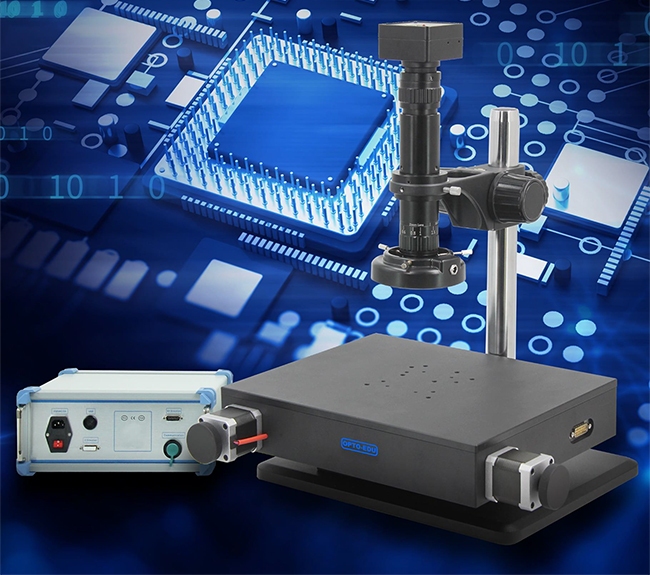
OPTOEDU offers the M11 motorized stereo series for different operator workflows. The M11.5805 emphasizes camera-first inspection through a mono zoom body, whereas the M11.5810 combines digital capture with binocular stereoscopic viewing.
Match the Optical Configuration to the Workflow
The OPTOEDU M11.5805 mono zoom configuration provides a 0.6×–5.0× optical zoom range and a 1:8.3 zoom ratio. Its 125 mm working distance leaves useful clearance above circuit boards, connectors, machined parts, and other solid samples.
The OPTOEDU M11.5810 binocular configuration uses a Greenough optical system, a 0.8×–5.0× trinocular head, a 1:6.3 zoom ratio, and WF10×/22 mm eyepieces. Its 45-degree viewing angle and 52–75 mm interpupillary adjustment suit users who need direct stereoscopic observation as well as camera documentation.
Check Working Distance and Sample Access
Working distance affects more than image focus. It determines whether a fixture, probe, soldering tool, tweezer, or taller component can fit below the optical head without restricting movement.
The M11.5805 specifies a 125 mm working distance, while the M11.5810 specifies 100 mm. The longer clearance favors camera-led inspection around bulky assemblies; the binocular model trades some clearance for direct stereo observation and hand-eye coordination.
Interpret XY Stage Specifications Correctly
The current product features a 100 × 100 mm XY scanning area and a stage motion resolution of 0.05 µm. Motion resolution is the smallest commanded stage increment; it is not the microscope’s optical resolution, measurement accuracy, or guaranteed repeatability.
A practical selection should also consider sample footprint, fixture size, revisit requirements, travel speed, and the stability of the complete system.
Select the Camera for Motion and Documentation
Both configurations list a 9 MP USB 3.0 global-shutter camera with a 1-inch CMOS sensor and C-mount interface. The specified frame rates are 34 fps at 4096 × 2160 and 60 fps at 2048 × 1080, giving users a choice between greater pixel coverage and faster live viewing.
A global shutter is valuable when the stage or sample is moving because the full frame is exposed at the same time. Camera performance should still be assessed together with illumination, exposure, field of view, calibration, and the smallest feature that must be documented.
Separate 2D Stitching from 3D Measurement
A motorized XY stage is well suited to planar scanning, free-area selection, automatic frame acquisition, and 2D image stitching. The resulting panorama can act as an electronic map, allowing the user to select an area and move the stage back to it for closer observation.
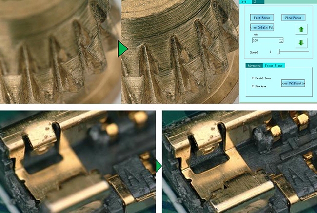
True automated focus stacking and 3D surface measurement require height information, so they depend on motorized Z control and the appropriate software and computer configuration. Buyers inspecting slopes, recesses, uneven coatings, or variable-height parts should confirm that the proposed system includes those components rather than assuming every XY model has them as standard.
Match the System to the Inspection Application
PCB and Electronic Component Inspection
Circuit boards often combine large inspection areas with small solder joints, pins, traces, and mounted components. Motorized XY scanning helps create a navigable overview, while the camera records localized details for comparison, annotation, and reporting.
The 125 mm working distance of the M11.5805 can provide additional access around taller connectors or fixtures. The M11.5810 is more suitable when an operator must manipulate a component while judging its shape through binocular stereo vision.
Machined Parts, Jewelry, and Surface Features
Metal parts, watch components, jewelry, fracture surfaces, and small mechanical assemblies may contain scratches, edges, recesses, and reflective areas. A stable stand, adjustable ring illumination, suitable working distance, and repeatable stage movement are therefore as important as nominal zoom range.
For flat polished parts, XY stitching may be sufficient to document a wider area. If the surface rises, tilts, or contains deep features, an XYZ configuration with autofocus or depth fusion is the more defensible choice.
Biological and Educational Samples
Low-magnification observation of plants, insects, and other relatively thick specimens can also benefit from a stereo workflow. Binocular observation supports spatial understanding, while digital capture makes it easier to share images and document selected regions.
The intended sample holder, lighting method, hygiene requirements, and desired image scale should be reviewed before adopting an industrial configuration for laboratory teaching. No clinical or diagnostic performance should be inferred without a separately validated application and protocol.
Choose Between M11.5805 and M11.5810
Choose M11.5805 for Camera-Led Automation
M11.5805 is the stronger fit when the inspection process is primarily monitor-based and depends on wide zoom coverage, longer working distance, automated XY scanning, and digital documentation. Its mono zoom design should not be described as offering the same direct stereoscopic experience as a Greenough binocular head.
Choose M11.5810 for Direct Stereo Observation
M11.5810 is the more natural choice for assembly, manipulation, and visual inspection that requires depth perception at the eyepieces. Its trinocular architecture preserves a camera path, allowing the same workstation to support operator viewing and image-based records.
The final decision should be based on the real specimen, fixture, smallest relevant feature, and expected inspection sequence. A demonstration using representative samples is more informative than comparing magnification alone, especially when lighting and surface reflectivity strongly affect visible detail.
Conclusion
The best motorized stereo microscope is the one whose optics, clearance, stage movement, camera, and software match the complete inspection workflow. OPTOEDU M11.5805 supports camera-led automated inspection, while M11.5810 adds binocular stereo viewing for tasks that require direct spatial judgment.
By separating standard XY stitching from optional Z-axis and 3D capabilities, users can select a system that is technically appropriate without paying for functions that do not serve the sample.
Explore the OPTOEDU M11 motorized microscope options to identify the configuration that fits your inspection workflow.
FAQ
Q: What is a motorized stereo microscope used for?
A: It is used to inspect and document solid samples while software controls sample movement across the field of view. Common tasks include PCB examination, component inspection, precision assembly, surface observation, wide-area image stitching, coordinate-based navigation, and repeated viewing of selected features.
Q: Is an XY motorized stage sufficient for 3D measurement?
A: An XY stage is sufficient for automated planar scanning and 2D panorama stitching. Automated focus stacking, depth fusion, and 3D surface measurement require height data, which normally means motorized Z control plus compatible software and computing hardware. The exact configuration should be confirmed before selection.
Q: Should I choose a mono zoom body or a binocular stereo head?
A: Choose a mono zoom body when inspection is primarily camera-based and digital capture or software operation dominates the workflow. Choose a binocular Greenough head when the operator needs direct depth perception for manipulation, assembly, or visual judgment. Working distance and zoom range should also be considered.
Q: Does 0.05 µm stage resolution mean 0.05 µm optical resolution?
A: No. Stage resolution describes the smallest commanded movement of the XY positioning system. Optical resolution depends on the optical design, wavelength, numerical aperture, camera sampling, illumination, and system calibration. Because a numerical aperture is not specified here, optical resolving power should be verified with representative samples.