The microscope for metal surface inspection should make harder-to-see features easier to see and not just brighter. For reflective surfaces, the same factors as for viewing reflective surfaces influence what can be seen: glare, viewing angle, depth of focus, surface texture. A useful setup for metal surface inspection therefore is a combination of suitable illumination and a stable setup for positioning and measuring the surface of the specimen.
The practical starting point is to define the defect or feature: a scratch, coating boundary, machined edge, pit, or raised mark. Then adjust illumination and viewing geometry around that target before increasing magnification. This approach reduces the risk of mistaking a bright reflection or shallow focus for a material defect.
Why Reflective Metal Is Difficult to Inspect
Reflection from a polished surface can reflect the light from the illuminator, the objective, or other nearby objects back into the optical path. This highlight can cover up a very shallow scratch in the surface, while a dark area between two clean edges can make it appear that the edge is damaged. Shifting magnification will not remove these artifacts, as they will just fill up more of the field of view.
In addition to these factors, the surface shape of the test piece also has to be considered. A flat test coupon, a turned test piece, or a recessed test part will all reflect light differently. A part with curved surfaces or steps will have some defects visible from one angle and hidden from another. Thus, the viewing angle and sample orientation must be considered as part of the inspection settings.
Choose Lighting for the Feature
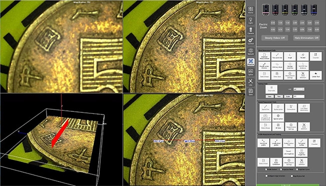
Start with a medium to light setting and look at the scene at low magnification to get a sense of the overall scene and locate the area of interest. Then at higher magnification, adjust the light intensity or direction in small steps while observing the feature of interest rather than the brightest part of the image.
Use Brightfield for General Surface Context
For locating boundaries, changes in surface finish, and large surface marks, a good starting point is the brightfield observation of the part surface. Even surfaces or small features against a background of different height or finish can be located with brightfield observation. However, very smooth surfaces will reflect light from the illuminator and obscure the image.
By tilting the specimen slightly, reflected light can be directed away from the part under examination. It is generally better to reduce excess illumination than to try to compensate for it later by altering camera exposure or by image processing. Such overexposed image data cannot be reliably recovered from the captured image.
Use Darkfield-Like Contrast for Edges and Texture
Scratches, particles, burrs, and sharp edges appear more pronounced when scattered by these features against the smooth surrounding surface when lit with oblique illumination. This type of lighting can be very useful for searching surfaces for defects but must be used with caution, as it can make normal texture appear worse than it really is. Verify any suspected defect by viewing it from an alternative angle of lighting or against an appropriate reference sample and record findings accordingly.
Dedicated darkfield illumination of an inspection system must be tested with samples. A label of “darkfield” does not guarantee that all defects become more visible. Part geometry, working distance, and the direction of the mark also play a big role.
Manage Glare with Polarization and Angle
The use of polarizing optics can help to reduce some of the surface reflection depending on the surface material and the optical design. It is important to compare polarized and unpolarized views of the actual surface. In many cases, a slight change in the part orientation or in the viewpoint will provide an adequate image without the need to add another optical mode.
Choose a Microscope for Metal Surface Inspection
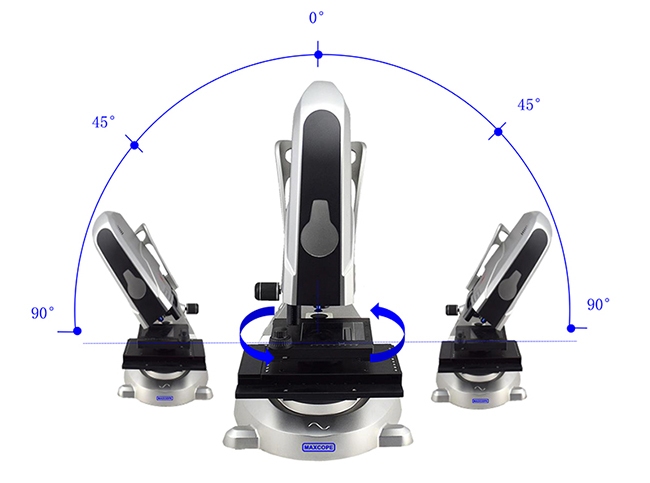
A metal surface inspection microscope needs to have sufficient space to place larger inspection components and sufficient optical resolution to inspect the desired surface feature. The working distance is important when parts have raised edges or are mounted on fixtures. A tilted view can also reveal sides that are not visible when looking straight down. A rotating stage allows the surface feature to be inspected while it is being rotated in different directions. The way a line or edge looks when viewed from different angles can be critical to its inspection.
Compare the part height and part footprint with the working distance and stage travel. Include the holder or part fixture in these measurements. A microscope that just focuses on a bare coupon may not have room to focus on the part with the component mounted.
Build a Repeatable Inspection Method
List the factors that will change the appearance of a reflective surface, and put them in a concise setup note. Other users can then easily find their way back to the same location, and compare later samples with similar viewing conditions. This also helps to clarify any later disagreements as to whether or not a material change has occurred.
Evaluate marks against a known-good part or a part of suitable reference. Take a wide view of the part first and then zoom in on the feature of interest. Make sure the image is properly scaled and oriented. Even if an image looks sharp, verify the measurement system’s calibration procedure and measurement limits as applicable to your application.
Clean surfaces to keep them free from loose dust, etc which can be mistaken for surface irregularities such as pits or scratches. Be cautious when cleaning surfaces with delicate coatings, as cleaning can damage them. Record any marks before cleaning using an approved method and re-measure/observe after cleaning to see if they have gone.
Where OPTOEDU Fits
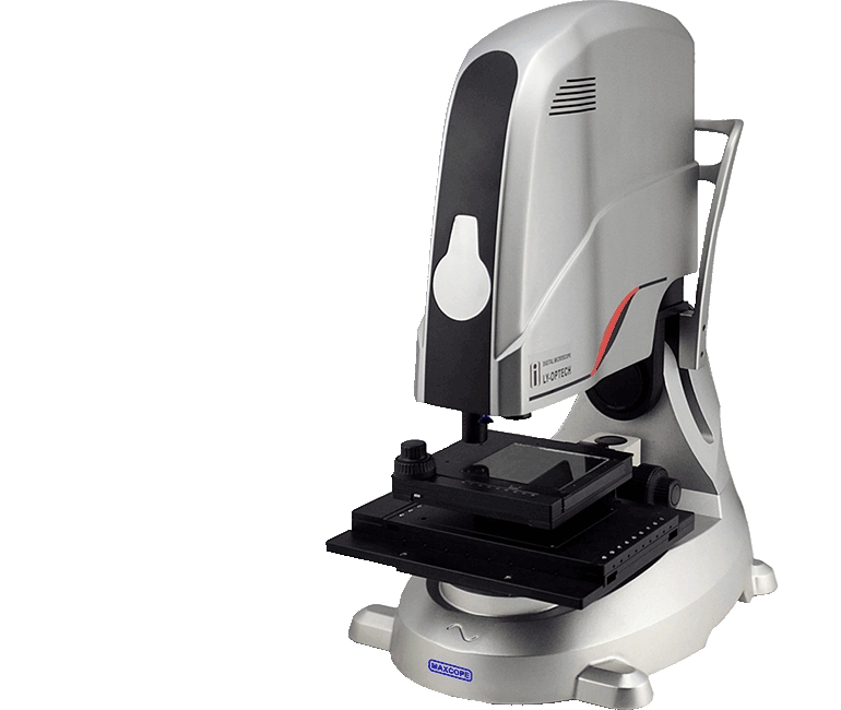
The M20.5830 is presented as a full-auto industrial microscope with motorized XYZ movement, a motorized nosepiece, and a tilting stand. Its listed product details include a 12x–8000x magnification range and metallurgical long-working-distance objectives.
The OPTOEDU M20.5830 industrial microscope can be compared with the full range of OPTOEDU motorized industrial microscopes when deciding on a suitable process. Specimen size and clearance, the amount of detail to be recorded, and whether observation is to be from an angle or in three dimensions all need to be taken into account.
Conclusion
A metal surface inspection microscope is primarily a tool for comparing identical features while keeping lighting and geometry as constant as possible. For very reflective parts, a low-glare view, sufficient working distance, and well-defined specimen position are more important than magnification. OPTOEDU’s M20.5830 metal surface inspection microscope is designed as a product with motorized movement and angled observation.
Contact us to check out the details for OPTOEDU M20.5830 for metal inspection.
FAQ
Q: Is a metallurgical microscope suitable for machined parts?
A: Yes, it could be suitable. You need to check the optical configuration, the working distance, and the clearance of the specimen. Typically, machined components have curved surfaces, recesses, etc. You should therefore test with representative parts and their respective fixturing. You also need to check that the setup can reach the desired location without contact and without having to re-mount the part.
Q: How can inspectors reduce glare under a microscope?
A: Decrease excessive illumination by changing the specimen or by changing the angle of view. Compare the view with different directions of light. In some cases, polarizing optics can be of help, but this strongly depends on the surface under investigation as well as on the optics used. Only take a photo when highlights and shadows no longer obscure the feature under investigation.
Q: What does a tilting microscope stand add to metal inspection?
A: Tilting a stand allows the inspector to view the sidewalls, slopes, etc. of parts that do not have a vertical surface when viewed from above. Surface geometry greatly affects how light reflects from surfaces under inspection. Use the same amount of tilt for all views, and record it when comparing images of different parts or for different inspections of the same part.