How can manufacturers inspect microscopic surface details on irregular components without suffering from shallow depth-of-field limitations? The definitive answer lies in upgrading to an all-in-one industrial 3D microscope, which solves this inspection bottleneck by combining automated focus sweeps with high-speed depth synthesis algorithms. Traditional optical platforms require constant manual adjustments and leave crucial target areas blurred, leading to expensive inspection delays. This integrated, motorized platform captures every microscopic peak and valley in perfect focus, delivering a fully compiled, metrology-grade three-dimensional rendering. By investing in advanced automated platforms, quality control departments can secure sub-micron repeatability and eliminate human operator subjectivity.
Why Traditional Inspections Require an Optical Upgrade
Standard optical microscopes are bound by a strict physical trade-off where depth of field decreases exponentially as magnification increases. When examining highly textured surfaces, such as fractured metals, steep connector pins, or multi-layered semiconductor packages, only a paper-thin slice of the specimen remains in focus. Operators must repeatedly turn manual focus knobs to construct a mental image of the part, which slows down throughput and introduces user-to-operator measurement variance.
Without plan-corrected motorized motion, capturing clear spatial data across steep elevation changes is physically impossible. Implementing an advanced optical platform resolves these physical boundaries by capturing a synchronized sequence of focal planes. The system then extracts the sharpest contrast coordinates to compile a single, fully focused composite image.
Why an All-in-One Industrial 3D Microscope is Essential for Modern Laboratories
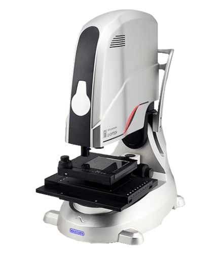
Modern industrial quality control requires high-resolution imaging combined with stable, automated mechanical movement. The OPTOEDU platform is engineered around an infinity-corrected APO objective array, featuring plan-apochromatic metallurgy lenses like the MPLSAPO 5X, 10X, 20X, 50X, and 100X series. These lenses correct chromatic and spherical aberrations across the entire visible spectrum, keeping target boundaries geometrically true. Generous working clearances, such as 80mm under a 1X lens and 2.1mm under a 100X objective, prevent accidental physical collisions with uneven specimens.
To achieve metrology-grade repeatable spatial coordinates, the microscope incorporates a high-performance piezoelectric displacement stage. By utilizing the inverse piezoelectric effect in specialized ceramics, this motorized stage moves with absolute mathematical consistency. It offers an XY motorized travel range of 110mm by 70mm with an outstanding step resolution of 0.05 µm. When coordinated with a motorized Z-axis 3D measuring microscope structure featuring a 120mm travel stroke and a Z-resolution of 0.1 µm, the platform scans through focus slices with micron-level stability.
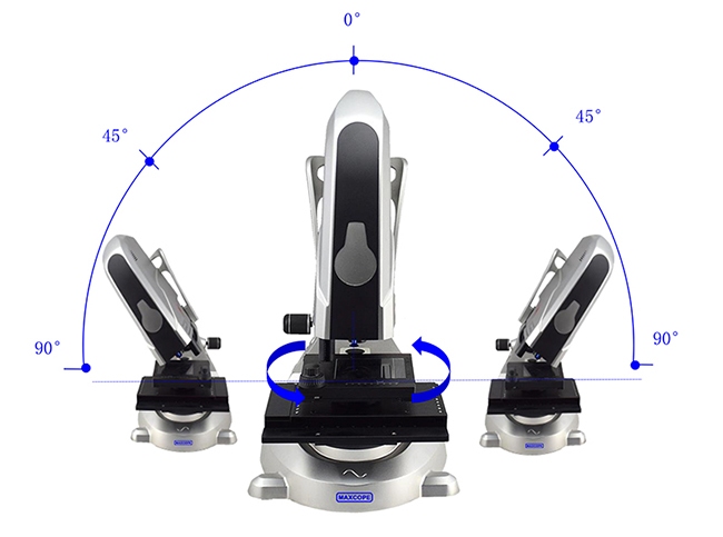
Furthermore, many physical defects are completely hidden from standard top-down vertical perspectives. Using a specialized tilting stand microscope base allows the entire optical head to incline up to +/-90 degrees relative to the working stage. Assisted by an ergonomic deflection handle and a 360-degree rotating manual stage, inspectors can comprehensively evaluate curved profiles and deep grooves from any side angle.
How to Reconstruct 3D Image of Object Surface with the OPTOEDU System
Setting the Focus Boundaries
Executing a high-resolution 3D reconstruction microscope profile with the OPTOEDU software is a streamlined, user-friendly process. The operator places the specimen on the piezoelectric displacement stage and adjusts the coarse focus to locate the target. Using the software controls, the operator drives the motorized Z-axis downward until the lowest topography of the sample becomes blurred, locking this coordinate as the Z-axis End Point. Next, the operator drives the stage upward until the highest peak of the sample passes through focus into blur, locking this coordinate as the Z-axis Start Point.
Processing with Advanced Synthesis Modes
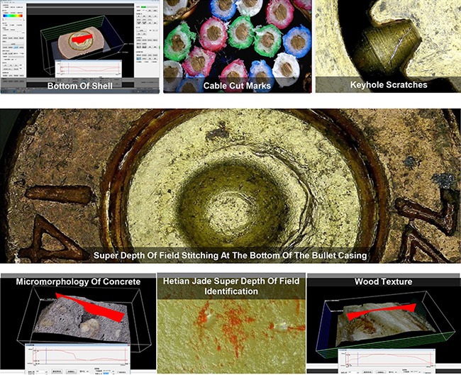
Once the focus boundaries are registered, the operator selects the scanning speed, choosing low speed for high-magnification objectives to maximize precision. Clicking Auto Composite triggers the motorized stage to step through the focus slices, compiling them into a true-color three-dimensional model in seconds. To match different material textures, the software supports four distinct reconstruction modes: regular, super precision mode, noise reduction, and plane height.
- Regular mode: displays raw, unprocessed spatial textures, suitable for fast previews.
- Super precision mode: removes image glitches and smooths measurement lines, recommended for fine dimensional metrology.
- Noise reduction mode: filters out sensor artifacts caused by uneven illumination, which is ideal for inspecting rough metal fractures.
- Plane height mode: specifically calibrated for extreme magnifications using 50X or 100X objectives.
How Does Large-Area Stitching Expand Inspection Capabilities
Serpentine XY Grid Scanning
For large components like integrated circuit wafers or complete coin faces, a single high-magnification field of view is insufficient. To overcome this field-of-view limit, the platform transforms into a high-resolution 3D stitching microscope. The operator defines the horizontal boundary limits by driving the motorized stage to the upper-left corner of the sample, resetting the XY coordinates to zero. The stage is then driven to the bottom-right corner of the entire specimen. By selecting 3D stitching, the motorized system automatically drives the stage in a serpentine grid pattern.
Automated Image Synthesis
At each grid intersection, the system performs a rapid vertical Z-focus sweep. The embedded software applies displacement correction and edge recognition to align adjacent fields of view seamlessly. This automated stitching process eliminates jagged boundaries and matches exposure values across the entire scanned area. The final output is a massive, high-megapixel panoramic 3D model that preserves micron-level surface height data across several square centimeters. Point cloud data can also be exported directly as standard TXT files containing XYZ coordinates for scientific research.
Conclusion
Adopting an all-in-one industrial 3D microscope equipped with infinity-plan metallurgical APO lenses and high-resolution stages represents a fundamental upgrade for industrial quality departments. By combining precise piezoelectric motorization with versatile software synthesis modes, this platform ensures that irregular micro-defects are measured with metrology-grade repeatability.
To explore customized system configurations for your assembly lines, please contact us.
FAQ
Q: What makes an OPTOEDU all-in-one industrial 3D microscope superior for semiconductor inspections?
A: The system breaks through standard optical limits by capturing a series of high-resolution images along a motorized Z-axis. It compiles these slices into a fully focused flat image and a metrology-grade 3D model, allowing accurate shape measurement of microscopic gold wires, solder balls, and semiconductor pins.
Q: How does the motorized Z-axis 3D measuring microscope structure improve measurement repeatability?
A: The motorized Z-axis structure features a travel range of 120mm and a sharp vertical step resolution of 0.1 µm. Controlled by advanced software, mouse wheels, or joystick inputs, it moves with mathematical consistency, completely removing human subjective errors from the vertical profiling process.
Q: Why should laboratories combine a tilting stand microscope with a piezoelectric stage?
A: Irregular samples often have deep holes or vertical pins hidden from top-down vertical views. A tilting stand microscope tilting +/-90 degrees allows multi-angle side-viewing, while the piezoelectric stage provides sub-micron XY positioning accuracy, ensuring complete 3D data capture of complex geometries.
Q: Can the OPTOEDU 3D reconstruction microscope analyze biological slices?
A: The system is heavily optimized for reflecting opaque materials, utilizing advanced coaxial and ring lights. Because it does not contain a bottom-transmitted backlight source, it is highly recommended for metals, semiconductors, and industrial parts rather than thin, transparent biological specimens.